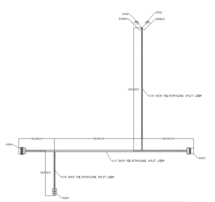
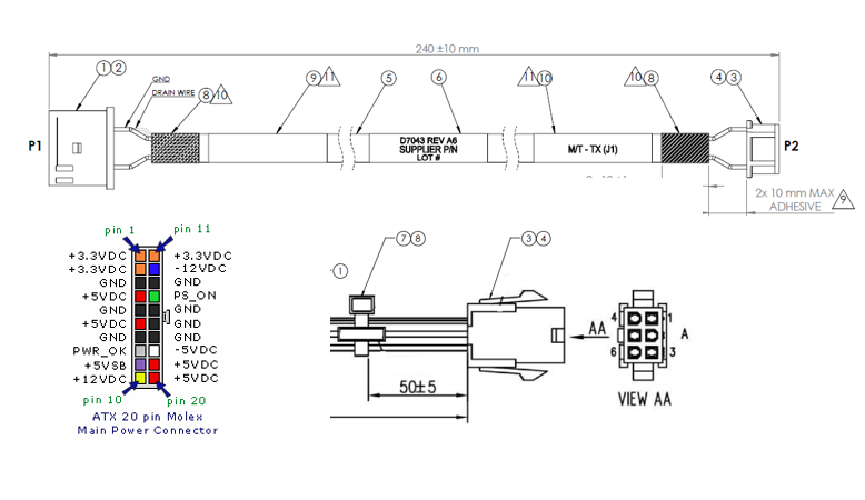
Creating a cable drawing that’s easy to understand and interpret can be pretty difficult, so here are a few pointers to help.

- Right angles are easiest to interpret but not always necessary.
- It should be clear where to measure dimensions from, like end of connector or back of connector (dimension lines are great!)
- Dimensions should be measurable from places which can be measured on a completed assembly (wire cut lengths can be hard to inspect). We will 100% check these in final inspection.
- Length tolerances should be wide enough to be easy to manufacture+/-5% is great. Use a -0 tolerance if nominal length is the shortest acceptable. (IPC has guidelines for this as well)
- Labels and heatshrink should appear on the drawing with dimensions and tolerances (or specified as “about” or “TYP”)
- Specifying the pinout of the connector, especially with colors, is very helpful. Best practice is 3rd angle projection of the connector face.
