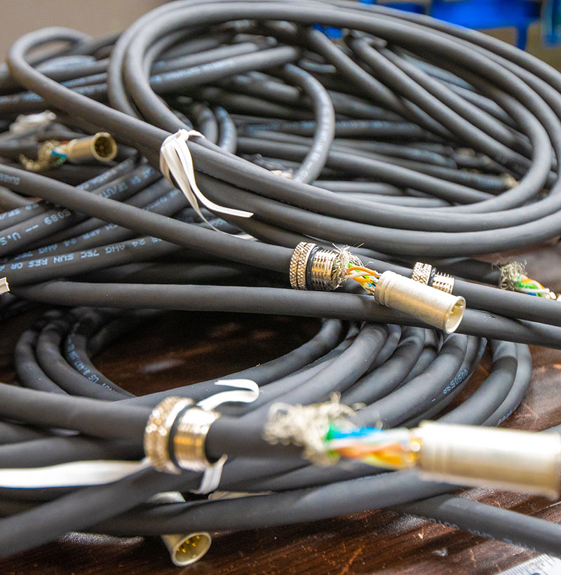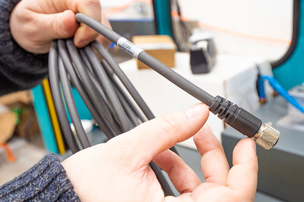
Technical Cable Applications, founded in 2002 and located in Auburn, WA, builds custom cable assemblies and wiring harnesses for original equipment manufacturers who need rugged, repeatable connections. Whether you need an established M12 cable assembly produced in volume, or a single prototype that has to survive a wash-down bay, our engineers and technicians can design, build, and test it in house. We manufacture standard configurations as well as fully custom cable assemblies, and we back both with an ISO 9001:2015 certified quality management system.
M12 cables are the connection of choice wherever data and power have to cross an unfriendly environment, and they have quietly replaced office-grade hardware across the plant floor. Below is a practical guide to how these cable assemblies are built, how to specify them, which connectors pair with them, and what our shop can do for the products you are bringing to market. Our M12 cables, connectors, and molded harnesses go into products across a dozen industries, from packaging lines to marine equipment.
Why Circular Threaded Connectors Took Over the Plant Floor
Industrial Ethernet has become the backbone of the modern factory, and the miniature circular connector standardized on the M12x1 thread has become the default hardware for carrying it. The reason is simple: an RJ45 plug was designed for an office wall, not for a machine that vibrates for twenty hours a day in the presence of oil mist and pressure washing.
A threaded circular shell solves several problems at once. The coupling nut clamps the mating faces together so vibration cannot back a contact out. The seal that forms between the plug and the receptacle keeps coolant, dust, and moisture away from the contacts, which is why these connectors are commonly specified to IP67, IP68, or IP69K ratings. The shell also gives molded cable assemblies a place to terminate the shield, so electrical noise has a low-impedance path to ground instead of coupling into the data pairs. Sealed connectors are what keep products running through a shift that would flood an unsealed jack.
Because the interface is compact — roughly 12 mm across the threads — it fits on the housing of a device that has no room for a full-size industrial connector. That combination of size, sealing, and mechanical retention has turned these into one of the default interface connectors on automation hardware, and it is why so many of the products our customers build depend on these cable assemblies. M12 cables now appear on nearly every class of equipment that has to report data back to a controller.
Codings, Pin Counts, and What They Are Used For
The most common point of confusion for buyers is coding. Shells look nearly identical across variants, but the keyway geometry differs so that incompatible circuits cannot be mated. Getting the coding right at the drawing stage prevents an expensive mistake at assembly.
A-coded connectors are the original and still the most common variant, used for sensor and actuator connections, DC power, and general device wiring in 3-, 4-, 5-, 8-, and 12-pin arrangements. A 4-pin A-coded cordset feeding a proximity switch is probably the most-installed of all M12 cables.
B-coded connectors are reserved for fieldbus applications such as PROFIBUS, so a bus drop cannot be plugged into a device port by accident. Products that ship into legacy bus networks still call for them.
C-coded connectors cover AC devices in older installations and appear less often on new equipment.
D-coded connectors carry four-conductor 100BASE-TX Ethernet at up to 100 Mbit/s and are the workhorse of installed industrial Ethernet. A large share of the M12 cables in service today use them.
X-coded connectors use eight shielded contacts arranged in four pairs, with an internal shield wall between quadrants, and support 1000BASE-T and 10GBASE-T. If you are specifying a new gigabit network, these are usually the connectors to choose.
L-coded and K-coded connectors exist specifically for DC and AC power transmission, while S- and T-coded variants serve related power roles in drive and control cabinets.
Pin count, coding, and shielding decisions all interact with the jacket and conductor set inside the cable, which is why it pays to specify complete cable assemblies as single part numbers rather than buying pieces and hoping they mate. Our engineers do that specification work with customers every week, and the resulting cable assemblies arrive ready to install.
Overmolded Cable Assemblies Versus Field-Wireable Hardware
There are two ways to get one of these connections onto the end of an industrial cable. The first is a field-wireable connector or an assembled back-shell, where a technician terminates conductors on site with screw or spring clamps. It is flexible, and it is the right answer for a repair or a one-off retrofit.
The second is an overmolded assembly, where the connector is molded directly onto the cable jacket in a controlled process. Overmolding is what we do in Auburn. Low-pressure injection molding forms a sealed, strain-relieved transition between the connector and the jacket, so there is no cavity for moisture to collect in and no screw terminal to loosen. The result is a part with consistent geometry, consistent electrical performance, and documented pull strength, produced the same way on the tenth unit and the ten-thousandth.
For products that ship to customers, molded M12 cables are almost always the better choice. Field terminations vary with whoever built them; molded connectors do not. Consistency matters most on products built in volume, where one bad termination in a hundred becomes a service problem instead of a rework ticket. They also handle motion better, which matters in robotics, gantries, and cable carriers where a cable may see millions of flex cycles across its service life. Continuous-flex cable is a different construction from static cable, and we will steer you toward the right one rather than let a static part fail in a carrier six months after launch.
Orientations, Keying, and Custom Pinouts
We mold both plugs and receptacles in the orientations your equipment layout actually requires. Male straight and right-angle connectors, female straight and right-angle connectors, single-ended pigtails, and double-ended M12 cables are all available, and keying position can be rotated to match the connector orientation on your housing. Shielded and unshielded cables can be built in any of those configurations.
That flexibility matters more than it sounds. A straight plug projecting 40 mm out of a drive housing is a part waiting to be sheared off by a passing pallet; a right-angle version routes the cable flat against the machine and survives. When customers send us a housing drawing, we work back from the available clearance to a configuration that will not become a warranty claim.
Because we build to your pinout and key configuration, we can also match legacy parts you already buy. Send us a sample, a print, or even a failed part pulled off a machine, and we can quote replacement cable assemblies built to the same interface. Custom pinouts, non-standard lengths, and mixed conductor counts are routine work here, not special requests.
Shielding, EMI, and Signal Integrity
Data and power rarely travel far apart in a modern cabinet. A shielded signal cable routed alongside a variable-frequency drive lead is exposed to fast switching transients that can corrupt packets, trip watchdogs, and cause intermittent faults that are miserable to diagnose.
We build shielded cable assemblies with continuous coverage along the full length, with the shield terminated 360 degrees at the connector shell rather than pigtailed to a single contact. That termination detail is the difference between a shield that works and a shield that is decorative. Foil-plus-braid constructions, drain conductors, and individually shielded pairs are all options depending on the electrical environment and the data rate the link has to support. Unshielded cables remain perfectly adequate for DC device power.
We also test what we build. Continuity and shield integrity checks are part of the process, and our cable testing and inspection services can be extended to customer-defined acceptance criteria when your quality group requires it.
Hybrid Harnesses: Mixing Connector Types in One Assembly
Very few machines use a single connector family. A typical panel carries a mix of circular industrial connectors, RJ45 jacks, rectangular power inlets, and board-level headers, and the harness that ties them together has to terminate all of them correctly.
This is where building both the molded parts and the harness under one roof pays off. We integrate M12 and M8 interfaces, standard RJ45, and other industry-specific or customer-specified connectors into single assemblies, drawing on connectors from Molex, TE, Hirose, JST, and other manufacturers. A breakout that starts as a molded circular cordset on the machine side and ends in a rectangular connector inside your enclosure is an ordinary job here.
Cable assemblies, cable protectors, and strain-relief hardware all have to be considered together for a harness that will be pulled through conduit or flexed daily. We will tell you when a construction choice is going to cause a problem down the line rather than quietly building to a print we know is marginal.
Industries We Support
Technical Cable Applications serves customers in industrial, telecommunications, medical, construction, energy, manufacturing, agriculture, and marine markets. The products in those sectors have very different requirements, and the cable assemblies that go into them reflect that.
In manufacturing and industrial automation, the priorities are flex life, sealing, and fast replacement. In telecommunications, it is data rate and shielding discipline. Medical products bring sanitization and material selection into the conversation. Construction and agricultural equipment sees UV exposure, abrasion, and temperature swings that destroy an indoor-rated cable in a season. Energy and marine products add corrosion, salt spray, and long service intervals where nobody wants to be pulling cable to replace a failed part. The cable that survives a wash-down dairy line is not the cable we would specify for agricultural products, and the connector plating usually changes with it.
Because we build to order rather than stocking a fixed catalog, the same molding and assembly capability serves all of these markets. The jacket material, shield construction, connector plating, and overmold geometry change from program to program; the process discipline behind the products does not.
How We Build These Products
Our shop combines automated equipment with skilled hand assembly. Automated cable cutting, stripping, and crimping give us repeatable terminations at volume. Cable is pulled from the spool, measured, and marked to your part number before it ever reaches a molding press. Injection molding and overmolding produce the sealed transitions described above. In-house 3D printing lets us produce fixtures and prototype housings quickly instead of waiting on an outside vendor. Final assembly is performed by IPC-certified technicians, and we build to the IPC/WHMA-A-620 Standard Revision E requirements.
Prototype development is part of the same workflow. We would rather build three samples and let your engineering group put them on a real machine than quote a production run against an unproven design. Once a design is validated, the documented process moves into production with the same tooling and the same work instructions, so what you qualified is what you receive.
We also build coaxial and RF cable assemblies, wiring harnesses, and molded cable products outside the circular-connector world. A customer with a mixed bill of materials that lists cable assemblies, cable glands, and connectors from several families can source all of it from one supplier instead of coordinating three.
Quality, Certifications, and Compliance
Quality claims are only worth what the documentation behind them proves, so here is exactly what we hold:
- ISO 9001:2015 certified quality management system, with our current certificate dated October 1, 2024.
- UL wiring harness certifications under file E363245 — ZPFW2.E363245 for the United States and ZPFW8.E363245 for Canada.
- ITAR registration, which allows us to work directly with defense and military contractors in the United States.
- IPC/WHMA-A-620 Standard Revision E workmanship requirements applied across our procedures.
- RoHS and REACH compliance documentation available on request. We produce parts to customer specifications and do not deviate from them without customer consent; verification of component-level compliance rests with the design authority for the product.
That certified quality system governs incoming cable and connector material, in-process checks, and the finished cable assemblies that leave the dock. A limited warranty applies to the parts we build, and our certificates are published on our certifications page so your supplier-qualification team can pull them directly.
Nearshore Manufacturing, Lead Times, and Order Quantities
Our main facility is in Auburn, WA, and we work with two partner facilities in Guadalajara, Mexico. That nearshore capacity does two useful things: it shortens lead times relative to overseas sourcing, and it lets us quote lower minimum order quantities, which matters when you are working on a prototype and do not want to manufacture thousands of units yet.
Both large and small production runs are supported. A validated design can be built in the quantity your program actually needs rather than the quantity a distributor’s stocking model prefers, and cable assemblies made in Auburn and in Guadalajara are held to the same inspection criteria. Cable and connectors for either location are purchased to the same drawings and specifications. Programs that start at fifty pieces and grow into thousands are common, and the part does not have to be re-qualified when the volume changes.
Specifying an Assembly: What to Send Us
A quote moves fastest when we have the following:
- Connector coding and pin count on each end, plus whether each end is a plug or a receptacle.
- Orientation and keying — straight or right-angle, and key position relative to your housing.
- Overall length and tolerance, measured the way you will inspect the finished cable.
- Jacket material and rating — PVC, PUR, or TPU, plus any oil, weld-slag, UV, or wash-down exposure.
- Shielding requirement and the data rate or protocol the link has to support.
- Flex requirement — static, occasional-motion, or continuous-flex duty, with expected cycle count.
- Environmental targets — ingress protection level, temperature range, chemical exposure.
- Cable construction preferences — conductor gauge, pair count, and any cable brand or part number you are standardizing on.
- Volume and schedule, including prototype quantity and expected annual usage.
If you do not have all of that, send what you have. Much of our work starts with a sketch and a phone call, and we fill in the specification with you.
Common Questions About These Cable Assemblies
Can you match a competitor’s part number? Sometimes. Send the print or a sample and we will either quote equivalent cable assemblies built to the same interface, coding, and length, cross-referencing the cable construction as well, or let you know what proprietary information prevents us from moving forward.
Do you stock standard M12 cables? We build to order rather than warehousing a catalog, which is what allows the custom pinouts, lengths, and jacket choices described above. Repeat programs are scheduled so the parts are ready when your line needs them.
How short or long can these cables be? Length is driven by the electrical requirement more than the process. For gigabit links, channel length limits apply; for power and device wiring, we build much longer runs. Tell us the application and we will confirm what is practical.
Can one assembly carry both power and data? Often, yes — either as a hybrid construction or as a pair of cable assemblies dressed together into one harness. Which approach is better depends on current, shielding, and the connectors available on your device.
Work With Our Team
Our reputation rests on parts that keep working long after they leave the building, and on excellent communication while a program is in flight. If you are evaluating cable solutions for your next design, we would like to be on that list. Standard solutions, custom solutions, prototypes, and long-running production programs all start the same way: a conversation about what the part has to survive. From a single prototype through a multi-year build, the cable products we ship are built to your drawing and inspected against your criteria.
Request a quote and we will get you an answer with real dates and real pricing.